Robotics is an exciting field that combines electronics, mechanics, and programming to create machines that can perform tasks autonomously. A line-following robot is one of the most popular beginner projects in robotics, and it’s an excellent way to learn about sensors, motors, and basic control systems. This step-by-step guide will walk you through building a simple line-following robot using affordable components like an Arduino, infrared (IR) sensors, and a motor driver.
By the end of this tutorial, you will have a working robot that can follow a line on the ground using its sensors to guide its movements. This project will help you understand the principles of robotics and lay the foundation for more advanced projects in the future.
Introduction to Line-Following Robots
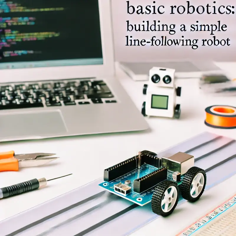
A line-following robot is designed to move along a path (usually a black line on a white surface) using sensors to detect the line’s position. The robot typically uses infrared sensors to differentiate between the line and the background. The sensors send data to a microcontroller, such as an Arduino, which processes the information and controls the motors to keep the robot on track.
Line-following robots are widely used in industrial automation, where they can transport materials along predefined paths. They are also popular in robotics competitions, where the objective is to complete a course as quickly and accurately as possible.
List of Required Components
Before you begin building your line-following robot, you’ll need to gather the necessary components. The following list includes the basic parts required for this project:
- Arduino Uno: The brain of your robot, responsible for processing sensor data and controlling the motors.
- Infrared (IR) Sensors: These sensors detect the presence of a line by measuring the reflectivity of the surface. Typically, you’ll use two or three IR sensors for a basic line-following robot.
- Motor Driver (L298N or L293D): This component allows the Arduino to control the motors by providing the necessary power and direction control.
- DC Motors with Wheels: These motors drive the robot forward, backward, and allow it to turn.
- Chassis: A basic robot chassis to mount all the components.
- Battery Pack: To power the motors and the Arduino. Typically, a 7.4V Li-ion battery pack is used.
- Breadboard and Jumper Wires: For connecting the components without soldering.
- Caster Wheel: A free-rotating wheel that supports the rear of the robot.
- Resistors (220 ohm): To limit the current to the IR sensors' LEDs.
Wiring the Circuit
Once you have all the components, the next step is to wire the circuit. Follow these steps to connect everything correctly:
- Mount the Components on the Chassis:
- Begin by attaching the DC motors to the chassis using screws or glue. Connect the wheels to the motor shafts.
- Attach the caster wheel to the rear of the chassis to provide balance.
- Secure the Arduino, motor driver, and battery pack to the chassis using double-sided tape or screws.
- Connect the IR Sensors:
- Place the IR sensors at the front of the robot, with the sensor’s detecting side facing down towards the ground.
- Connect the VCC pin of each IR sensor to the 5V pin on the Arduino.
- Connect the GND pin of each IR sensor to the GND pin on the Arduino.
- Connect the OUT pin of each IR sensor to an available digital input pin on the Arduino (e.g., pins 2 and 3).
- Wire the Motor Driver to the Motors and Arduino:
- Connect the two DC motors to the output pins (OUT1, OUT2, OUT3, OUT4) of the motor driver.
- Connect the input pins of the motor driver (IN1, IN2, IN3, IN4) to four available digital output pins on the Arduino (e.g., pins 8, 9, 10, 11).
- Connect the VCC pin of the motor driver to the battery pack’s positive terminal and the GND pin to the battery pack’s negative terminal.
- Connect the motor driver’s 5V pin to the 5V pin on the Arduino and the GND pin to the Arduino’s GND pin.
- Power the Arduino:
- Connect the battery pack’s positive and negative terminals to the VIN and GND pins on the Arduino to power the entire circuit.
At this point, all the components should be securely mounted on the chassis, and the wiring should be complete. Double-check all connections to ensure there are no loose wires or incorrect connections.
Writing the Code to Control the Motors Based on Sensor Input
Now that the hardware is ready, it’s time to write the code that will control the robot’s behavior. The code will read the sensor data and adjust the motor speeds to keep the robot following the line.
Here’s a simple example code:
// Define the sensor and motor pins
int sensorLeft = 2;
int sensorRight = 3;
int motorLeftForward = 8;
int motorLeftBackward = 9;
int motorRightForward = 10;
int motorRightBackward = 11;

void setup() {
  // Set the sensor pins as inputs
  pinMode(sensorLeft, INPUT);
  pinMode(sensorRight, INPUT);

  // Set the motor pins as outputs
  pinMode(motorLeftForward, OUTPUT);
  pinMode(motorLeftBackward, OUTPUT);
  pinMode(motorRightForward, OUTPUT);
  pinMode(motorRightBackward, OUTPUT);
}

void loop() {
  // Read the sensor values
  int leftValue = digitalRead(sensorLeft);
  int rightValue = digitalRead(sensorRight);

  // Determine the robot's movement based on sensor input
  if (leftValue == LOW && rightValue == LOW) {
    // Both sensors on the line, move forward
    moveForward();
  } else if (leftValue == LOW && rightValue == HIGH) {
    // Left sensor on the line, turn left
    turnLeft();
  } else if (leftValue == HIGH && rightValue == LOW) {
    // Right sensor on the line, turn right
    turnRight();
  } else {
    // Both sensors off the line, stop
    stopRobot();
  }
}

void moveForward() {
  digitalWrite(motorLeftForward, HIGH);
  digitalWrite(motorLeftBackward, LOW);
  digitalWrite(motorRightForward, HIGH);
  digitalWrite(motorRightBackward, LOW);
}

void turnLeft() {
  digitalWrite(motorLeftForward, LOW);
  digitalWrite(motorLeftBackward, HIGH);
  digitalWrite(motorRightForward, HIGH);
  digitalWrite(motorRightBackward, LOW);
}

void turnRight() {
  digitalWrite(motorLeftForward, HIGH);
  digitalWrite(motorLeftBackward, LOW);
  digitalWrite(motorRightForward, LOW);
  digitalWrite(motorRightBackward, HIGH);
}

void stopRobot() {
  digitalWrite(motorLeftForward, LOW);
  digitalWrite(motorLeftBackward, LOW);
  digitalWrite(motorRightForward, LOW);
  digitalWrite(motorRightBackward, LOW);
}
Explanation of the Code:
- Sensor Reading: The code reads the values from the left and right IR sensors. If the sensor detects a line, it will return
LOW(indicating a dark surface like a black line), and if it does not detect a line, it will returnHIGH(indicating a light surface). - Movement Logic: The robot’s movement is determined based on the sensor input. If both sensors detect the line, the robot moves forward. If only the left sensor detects the line, the robot turns left, and if only the right sensor detects the line, the robot turns right. If neither sensor detects the line, the robot stops.
Testing and Adjusting the Robot’s Performance
Once you’ve uploaded the code to the Arduino, it’s time to test your line-following robot. Here’s how to go about it:
- Prepare a Test Track:
- Create a simple test track using black electrical tape on a white surface or use a pre-printed track. Ensure the track has curves and straight sections to test the robot’s performance in different scenarios.
- Place the Robot on the Track:
- Position your robot on the starting line of the track, ensuring the sensors are aligned over the line.
- Power On the Robot:
- Turn on the power supply and observe how the robot behaves. The robot should follow the line smoothly without veering off.
- Adjust Sensor Sensitivity:
- If the robot struggles to follow the line, you may need to adjust the sensor sensitivity. This can be done by modifying the code to introduce small delays or adjust the threshold values for sensor readings.
- Tuning the Motors:
- If the robot moves too fast or too slow, you can adjust the motor speed in the code. Reducing the speed may help the robot navigate turns more accurately.
- Fine-Tuning the Code:
- Depending on the robot’s performance, you may need to fine-tune the code further. For example, you can add conditions for sharper turns or smoother transitions between straight and curved sections of the track.
- Test Again:
- After making adjustments, test the robot again to see if the performance has improved. Continue this process until the robot can consistently follow the line without issues.
Conclusion
Building a line-following robot is a fantastic project for beginners in robotics. It introduces key concepts such as sensor integration, motor control, and basic programming, all of which are essential skills for more complexprojects in the future. Throughout this guide, you’ve learned how to set up your robot’s hardware, write the control code, and fine-tune the system to ensure smooth operation.
This project not only gives you hands-on experience with essential robotics components but also enhances your problem-solving skills as you work to optimize your robot's performance. As you gain confidence, you can expand on this project by adding features such as obstacle avoidance, speed control, or even integrating wireless control. The possibilities are endless, and with the foundation you've built here, you're well on your way to becoming a proficient robotics engineer. Happy building!


